Wi-Fi Integration with ESP8266 module
The ESP8266 has become an essential component in electronics, offering an affordable and compact means to integrate Wi-Fi connectivity into various projects. This tiny module has attracted a broad spectrum of users all aiming to implement smart home systems, IoT devices, and remote monitoring solutions. With its compact size, low power consumption, and seamless integration with Wi-Fi networks, the ESP8266 empowers innovators to create groundbreaking solutions in the digital age. The ESP8266 offers a user-friendly platform to bring your ideas to life. In this article, we will examine a particular variant of ESP8266 modules, specifically the ESP-01.
Prerequisites
For in-depth comprehension of AT commands refer to our article: The Complete Handbook of AT Commands.
Components
| 1x Arduino Nano (or another Arduino module)
|
| 1x Mini-breadboard
|
| 1x ESP8266 module $1.61 |
| 1x ESP8266 breadboard adapter (recommended)
|
| 1x ESP8266 Arduino adapter (recommended) $1.23 |
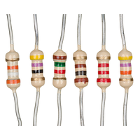
| Resistors kit $3.43 |
| Dupont wires
|


Module variations
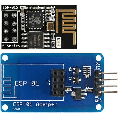
The naming convention for the ESP8266 series of modules can be a bit confusing. The ESP8266 is actually the name of the microcontroller chip that powers these modules. However, when referring to specific modules within the ESP8266 series, such as the ESP-01 and ESP-01S, the naming convention typically includes a prefix indicating the module type followed by a number. In the case of the ESP-01 and ESP-01S, ESP stands for Espressif Systems Platform, the manufacturer of the ESP8266 chip, while 01 is simply a designation assigned to these particular modules.
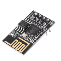
So, the ESP-01S, an upgraded version of the ESP-01, boasts enhanced RF performance and stability, thanks to its improved PCB antenna. This enhancement ensures superior signal reception and transmission capabilities, making it suitable for projects requiring robust wireless connectivity. It's important to note that the ESP-01S offers more memory compared to the ESP-01. This increased memory capacity equips developers with additional space to store program code and data, enabling more complex and feature-rich applications.
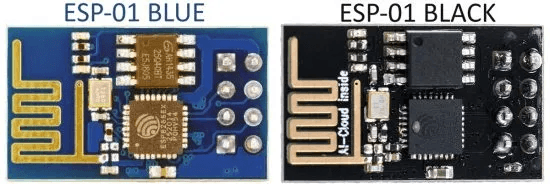
Moreover, there is a noticeable color difference between the ESP-01 and the ESP-01S. The ESP-01 typically features a blue Printed Circuit Board (PCB), while the ESP-01S usually has a black PCB. This color variation aids in visually distinguishing between the two variants, particularly when working on projects with multiple modules or in situations where color-coding is advantageous.
Feature | ESP-01 | ESP-01S |
|---|---|---|
Flash Memory | 512 KB | 1 MB |
Color | Blue | Black |
LEDs | 2 | 1 |
Programmable LEDs | - | 1 |
In summary, although the ESP-01 and ESP-01S share similarities, their primary differences are found in the flash memory chip and the LED configuration on GPIO2.
Wiring schema
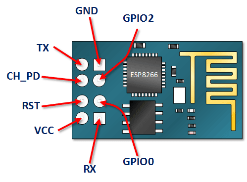
The wiring schema of the ESP-01 module starts with a description of its pinout, offering essential insights into the module's connections and functionalities.
Pin Name | Pin Function | Description |
|---|---|---|
VCC | Power supply (3.3V) | The VCC pin provides a 3.3-volt power supply |
GND | Ground | The GND pin connects the board to ground |
TX | Transmit Data | The TX pin is used for transmitting data |
RX | Receive Data | The RX pin primary function is to receive data |
CH_PD | Chip Power Down (Active High) | The CH_PD pin enables the chip when pulling it high |
RST | Reset (Active Low) | The RESET pin resets the board when this pin is pulled low |
GPIO0 | General-purpose I/O 0 | A general-purpose input/output pin |
GPIO2 | General-purpose I/O 2 | Another general-purpose input/output pin |
Given that many commercially available devices operate on 5V logic, there is a risk of damage when directly connecting them with the ESP8266 module. It is important to note that each input signal to the ESP8266 should not exceed 3.3V, necessitating the use of a voltage divider for each signal departing to the module.
When it comes to Arduino, the 3.3V signal serves solely as a power supply, while other signals, including PWM, communication, and digital signals, function at 5V. To overcome this challenge, one solution involves using a voltage divider comprising a 10Kohm resistor and a 20Kohm resistor. Here's how you can wire them together:
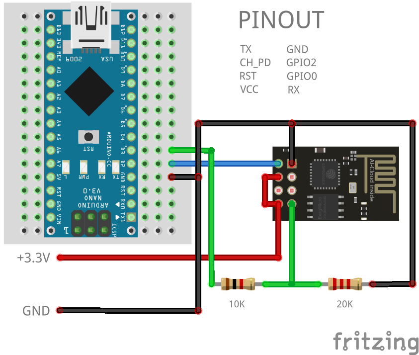
Connect an external power source supplying 3.3V to the VCC pin of the ESP8266 module to power it. Additionally, enable the module by connecting the CH_PD pin to the 3.3V pin.
Connect the common ground to the Arduino and ESP8266 module respective ground (GND) pins.
Connect the RX pin of the Arduino to the TX pin of the ESP8266 module.
This connection does not require a voltage divider. This is because the ESP8266's TX pin outputs signals at 3.3V logic levels, which are compatible with the Arduino module's TX pin operating at 5V logic levels.Connect the TX pin of the Arduino to the RX pin of the ESP8266 module via a voltage divider.
Use a voltage divider circuit with a 10Kohm resistor connected between the TX pin of the Arduino and the RX pin of the ESP8266 module. Additionally, connect a 20Kohm resistor between the RX pin of the ESP8266 module and ground (GND). The junction between the two resistors will provide the appropriate voltage level for the RX pin of the ESP8266 module.
The voltage divider setup ensures that the 5V output from the Arduino's TX pin is reduced to approximately 3.3V, which is safe for the ESP8266 module. Make sure to double-check your connections and use appropriate resistor values to achieve the desired voltage reduction.
Breadboard adapter for ESP-01
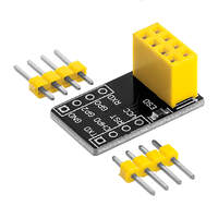
When setting up a breadboard, inserting the ESP-01 module directly is not viable. Previously, several methods were employed to adapt the ESP-01 module for breadboarding, including bending the header pins or crafting a DIY adapter. Fortunately, affordable breadboard adapters specifically designed for the ESP-01 module are now readily accessible, as shown in the figure below.
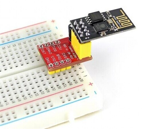
While it's not mandatory, it's advisable to use these boards to simplify the wiring process.
Arduino adapter for ESP-01
When connecting the ESP-01 board to an Arduino board, it's important to consider the following points:
Avoid powering the ESP-01 module with the 3.3V output from the Arduino board. The ESP-01 module may demand up to 300mA of current, potentially causing the 3.3V regulator on the Arduino board to overheat and sustain damage.
Implement logic level translation between the ESP-01 and the Arduino board. The Arduino board operates on 5V logic, whereas the ESP-01 module operates on 3.3V logic.
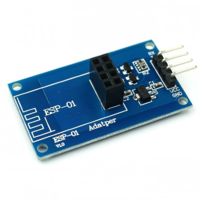
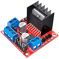
Below is an image of a suitable ESP-01 adapter designed for interfacing with Arduino boards.
This adapter features a built-in 3.3V regulator and two bi-directional logic level converters for the RX and TX pins.
AT Instruction set
The AT instruction set is a set of commands that can be used to communicate with the ESP8266 module via a serial interface. These commands, often referred to as AT commands, allow users to configure various settings, control functionalities, and retrieve information from the module. By sending simple text-based commands over a serial connection, users can interact with the module without needing to write complex code or understand the intricacies of the module's firmware.
This makes the ESP8266 module accessible to a wide range of users, from beginners to experienced developers, enabling rapid prototyping and development of Wi-Fi-enabled projects. Additionally, the AT instruction set provides a standardized interface for interacting with the module, making it easier to integrate the ESP8266 into existing systems and frameworks.
Detailed information on using AT commands is available in our Complete Handbook of AT Commands.
Arduino Code
In this article, we will explore the basic communication between an ESP8266 and an Arduino. Users may input any AT command via the Serial Monitor to interact with the ESP8266 module. Remember to configure the Serial Monitor to use both NL (New Line) and CR (Carriage Return).
#include "SoftwareSerial.h"

#define RX_PIN 2
#define TX_PIN 3

SoftwareSerial SerialEsp(RX_PIN, TX_PIN);

void setup()
{
  // Begin serial communication with the host computer
  Serial.begin(115200);
  Serial.println("Remember to to set Both NL & CR in the serial monitor.");

  // Begin serial communication with the ESP8266 module
  SerialEsp.begin(115200);
  Serial.println("ESP8266 module is ready");
}

void loop()
{
  // We have available information to read
  if (SerialEsp.available()) {
    Serial.write(SerialEsp.read());
  }

  // We have available information to write
  if (Serial.available()) {
    SerialEsp.write(Serial.read());
  }
}
Ensure to select the appropriate baud rate for both the serial monitor and the ESP8266 module. If you need to update the baud rate of your module, please consult the baudrate sketch provided in our official GitHub repository.
Testing
Once the code has been uploaded and everything is initialized, we can start communication with the ESP8266 module using the serial monitor and AT commands.
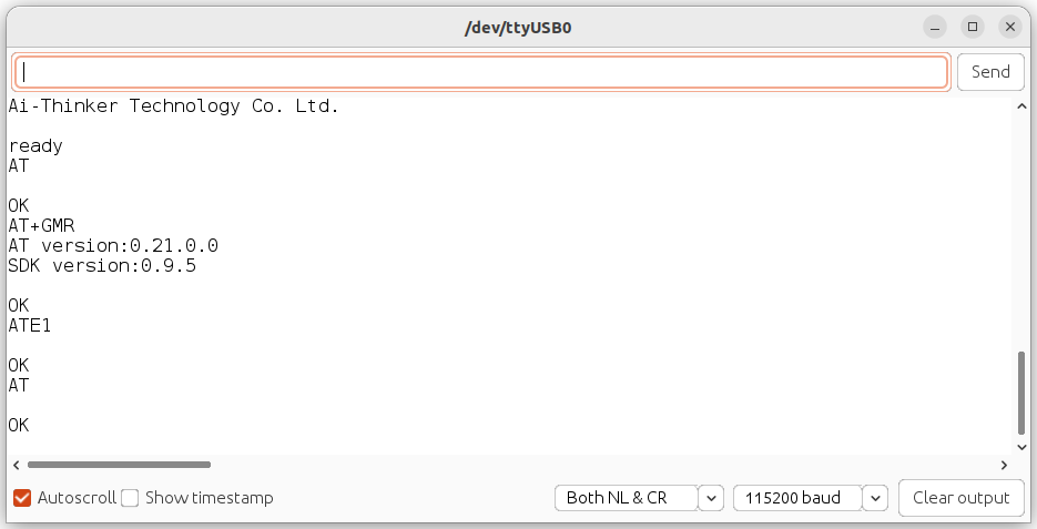
You should come across responses similar to those shown in the image above. Now you can easily connect to your WiFi network using the following AT command:
// Set the module to Station mode
AT+CWMODE=1

// Connect to the Wi-Fi network
AT+CWJAP="Your WiFi SSID","Your WiFi password"
Congratulations! You've just stepped into an exciting area of IoT (Internet of Things). Connecting your local device to the internet opens up many new possibilities for your projects.
Conclusion
The ESP8266 modules offer practical solutions for incorporating Wi-Fi connectivity into electronic projects. Their compact design, enhanced features, and compatibility with various applications empower developers to innovate across smart homes, IoT devices, industrial automation, and beyond. As technology advances, the ESP8266 series remains a dependable platform, enabling smooth connectivity and driving the creation of innovative solutions.
Credits
Official GitHub: https://github.com/hibit-dev/ESP8266


0 Comments