Wi-Fi Integration made easy with ESP8266WiFi library
The ESP8266 is a low-cost Wi-Fi microchip with full TCP/IP stack and microcontroller capability, created by Espressif Systems. It's popular among hobbyists and developers for its affordability and ease of use, making it a go-to choice for various IoT projects. When paired with the ESP8266WiFi library, this tiny module becomes even more powerful, simplifying the process of connecting devices to Wi-Fi networks and enabling a multitude of creative applications.
Prerequisites
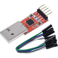
To gain a deeper understanding of the ESP8266 module, we recommend reading the article on Wi-Fi Integration with ESP8266 module, which provides an introduction to the module and its setup. We also recommend checking out the serial USB module description at Interfacing USB to Serial converter module.
Components
| 1x ESP8266 module $1.61 |
| 1x USB Serial adapter
|
| 1x Mini-breadboard (recommended)
|
| 1x ESP8266 breadboard adapter (recommended)
|
| 1x ESP8266 Arduino adapter (recommended) $1.23 |
| Resistors kit $3.43 |
| Dupont wires
|


Wiring schema
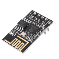
The wiring schema of the ESP-01 module starts with a description of its pinout, offering essential insights into the module's connections and functionalities.
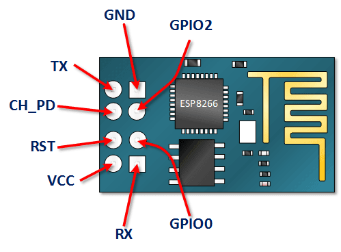
Pin Name | Pin Function | Description |
|---|---|---|
VCC | Power supply (3.3V) | The VCC pin provides a 3.3-volt power supply |
GND | Ground | The GND pin connects the board to ground |
TX | Transmit Data | The TX pin is used for transmitting data |
RX | Receive Data | The RX pin primary function is to receive data |
CH_PD | Chip Power Down (Active High) | The CH_PD pin enables the chip when pulling it high |
RST | Reset (Active Low) | The RESET pin resets the board when this pin is pulled low |
GPIO0 | General-purpose I/O 0 | A general-purpose input/output pin |
GPIO2 | General-purpose I/O 2 | Another general-purpose input/output pin |
Given that many commercially available devices operate on 5V logic, there is a risk of damage when directly connecting them with the ESP8266 module. It is important to note that each input signal to the ESP8266 should not exceed 3.3V, necessitating the use of a voltage divider for each signal departing to the module.
Before you can perform any updates, you need to properly connect your ESP8266 to your computer. Here's a step-by-step guide to the wiring schema:
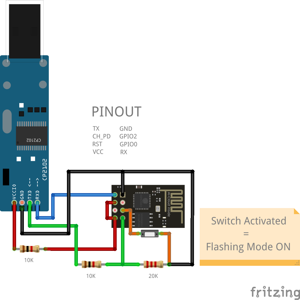
Connect the 5V output of the CP2102 adapter to the VCC pin of the ESP8266 module to power it. Since the ESP8266 operates on 3.3V, do not connect it directly to 5V. Use a voltage regulator or a resistor divider to reduce the voltage to 3.3V. Additionally, enable the module by connecting the CH_PD pin to the 3.3V pin.
Connect the GND pin of the CP2102 adapter to the GND pin of the ESP8266 to complete the circuit.
Connect the RX pin of the CP2102 adapter to the TX pin of the ESP8266 module.
This connection does not require a voltage divider. This is because the ESP8266's TX pin outputs signals at 3.3V logic levels, which are compatible with the CP2102 module's TX pin operating at 5V logic levels.Connect the TX pin of the CP2102 adapter to the RX pin of the ESP8266 module via a voltage divider.
Use a voltage divider circuit with a 10Kohm resistor connected between the TX pin of the CP2102 adapter and the RX pin of the ESP8266 module. Additionally, connect a 20Kohm resistor between the RX pin of the ESP8266 module and ground (GND). The junction between the two resistors will provide the appropriate voltage level for the RX pin of the ESP8266 module.To enter the flashing mode, connect GPIO0 to the ground (GND) before powering on or resetting the ESP8266. This is necessary for uploading new code to the ESP8266 module and can be easily accomplished by turning the switch button ON. When the code has been uploaded and you only want to use the module, the switch must be turned OFF.
The voltage divider setup ensures that the 5V output from the Arduino's TX pin is reduced to approximately 3.3V, which is safe for the ESP8266 module. Make sure to double-check your connections and use appropriate resistor values to achieve the desired voltage reduction.
Breadboard adapter for ESP-01
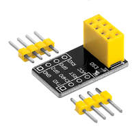
When setting up a breadboard, inserting the ESP-01 module directly is not viable. Previously, several methods were employed to adapt the ESP-01 module for breadboarding, including bending the header pins or crafting a DIY adapter. Fortunately, affordable breadboard adapters specifically designed for the ESP-01 module are now readily accessible, as shown in the figure below.
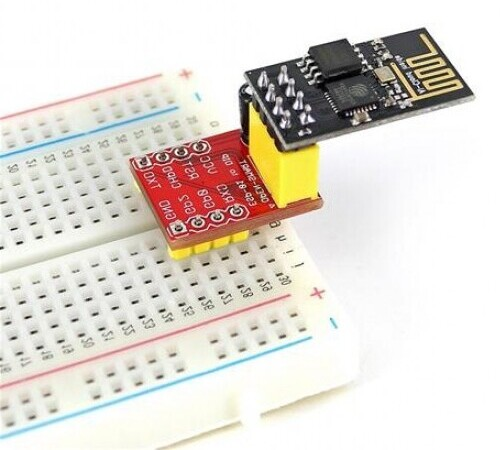
While it's not mandatory, it's advisable to use these boards to simplify the wiring process.
Arduino adapter for ESP-01
When connecting the ESP-01 board to an Arduino board, it's important to consider the following points:
Avoid powering the ESP-01 module with the 3.3V output from the Arduino board. The ESP-01 module may demand up to 300mA of current, potentially causing the 3.3V regulator on the Arduino board to overheat and sustain damage.
Implement logic level translation between the ESP-01 and the Arduino board. The Arduino board operates on 5V logic, whereas the ESP-01 module operates on 3.3V logic.
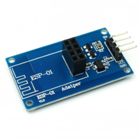
Below is an image of a suitable ESP-01 adapter designed for interfacing with Arduino boards.
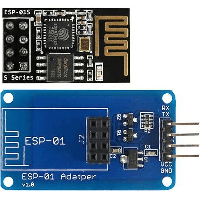
This adapter features a built-in 3.3V regulator and two bi-directional logic level converters for the RX and TX pins.
Install ESP8266WiFi library
The ESP8266WiFi library abstracts the complexities of Wi-Fi communication, providing a simple and straightforward way to connect your projects to the internet. This library includes a variety of features, such as network scanning, connecting to a network, and managing multiple connections. By using the ESP8266WiFi library, developers can focus more on their application's core functionality rather than getting bogged down with networking details.
The Wi-Fi library for ESP8266 has been developed based on ESP8266 SDK, using the naming conventions and overall functionality philosophy of the Arduino WiFi library. Before using the library, there's a configuring step for ESP8266 board.
ESP8266 board configuration
Navigate to the File menu and select Preferences. In the Preferences window, you will find a field labeled Additional Board Manager URLs. Here, you need to enter the following URL:
http://arduino.esp8266.com/stable/package_esp8266com_index.json
After pasting the URL, save your changes and close the Preferences window.
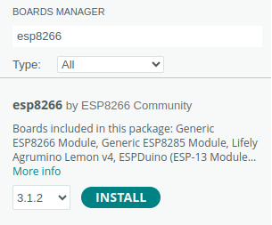
Next, you need to install the ESP8266 board package. To do this, go to the Tools menu, hover over Board, and then click on Boards Manager. A new window will open, allowing you to manage different board packages. In the search bar at the top of this window, type ESP8266. Look for the esp8266 by ESP8266 Community package and click on the install button next to it. This process may take a while, so be patient while the package is being downloaded and installed.
After the installation is complete, you need to select the appropriate ESP8266 board from the list. Go back to the Tools menu, hover over Board, and scroll through the list of available boards until you find the one that matches your hardware, such as ESP8266 Generic Module. Click on it to select it as your active board.
From this point forward, you can simply use the include statement:
#include "ESP8266WiFi.h"
It will include the library with predefined functions to interact with the module.
ESP8266 Code
In the following snippet, you can see a quick start sketch that allows you to connect to an available WiFi network. Just replace the defined constants with your network credentials.
#include "ESP8266WiFi.h"

#define NETWORK_NAME "network-name"
#define NETWORK_PASS "network-pass"

void setup()
{
  // Begin serial communication with the host computer
  Serial.begin(115200);
  Serial.println();

  //Wait
  delay(500);

  // Begin wireless communication with the network
  WiFi.begin(NETWORK_NAME, NETWORK_PASS);

  Serial.print("Connecting");
  while (WiFi.status() != WL_CONNECTED) {
    delay(500);
    Serial.print(".");
  }
  Serial.println();

  // Successfully connected
  Serial.println("Connected");
  Serial.print("IP address: ");
  Serial.println(WiFi.localIP());
}

void loop()
{
  // Your loop code
}
The ESP8266WiFi library offers a wide range of possibilities and applications. Below, we have outlined some potential use cases. For detailed examples, visit the code available in our GitHub repository.
Flashing ESP8266 code
To upload new code to the module, it must be set to flashing mode as specified in the wiring schema. The upload process may take some time and will produce output similar to the image shown below.
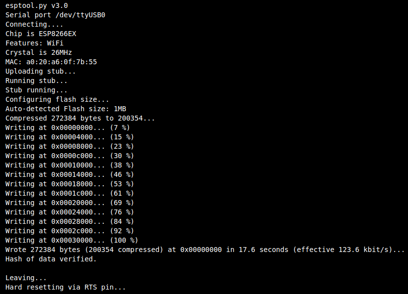
Once the upload is complete, disconnect the module, turn off flashing mode, and reconnect it to begin using it.
Testing ESP8266 code
When connected, the ESP8266 module will attempt to join the specified WiFi network and display the results in the serial monitor. You should come across responses similar to those shown in the image below.
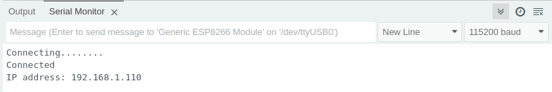
Your device now has an internet connection, unlocking numerous new possibilities for your projects.
Conclusion
The ESP8266, combined with the ESP8266WiFi library, provides a powerful and accessible platform for a wide range of IoT projects. Its ease of use, combined with the flexibility and features of the library, allows developers to quickly and effectively bring their ideas to life. Regardless of whether you're creating simple Wi-Fi enabled devices or more complex systems, the ESP8266 and its corresponding library provide a reliable framework for innovation and connectivity.
Credits
Official GitHub: https://github.com/hibit-dev/ESP8266
Official ESP8266WiFi: https://arduino-esp8266.readthedocs.io
This article is available to HiBit members only.
If you're new to HiBit, create a free account to read this article.


0 Comments