Understanding SIPO Shift Registers
Shift registers are integral components in digital electronics, enabling efficient data management and transfer. When working on Arduino projects, you may quickly run into the issue of not having enough output pins to control all your components. This is where SIPO (Serial-In, Parallel-Out) shift registers come into play. These devices allow you to manage multiple outputs with just a few pins on your Arduino, making them a powerful tool for more complex projects involving numerous LEDs, buttons or other peripherals. This article explores why shift registers are necessary, how they function, and their practical applications with Arduino.
SIPO vs PISO shift registers
Shift registers are available in two main types: SIPO (Serial-In, Parallel-Out) and PISO (Parallel-In, Serial-Out). SIPO registers are ideal for managing multiple outputs, like controlling arrays of LEDs, whereas PISO registers excel at collecting multiple inputs, such as reading states from buttons.
The 74HC595 is a widely used SIPO chip, while the 74HC165 is the go-to PISO chip.
Components
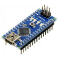
| 1x Arduino Nano (or another Arduino module)
|
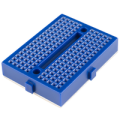
| 2x Mini-breadboard
|
| 1x 74HC595 shift register $1.53 |
| 8x LED
|
| 8x 220 ohm resistor
|
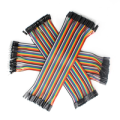
| Dupont wires
|


Understanding SIPO shift registers
A SIPO shift register operates by taking data input serially and then outputting it in parallel. The process works as follows:
Data Entry: data is sent to the shift register one bit at a time.
Clock Synchronization: the clock signal synchronizes the shifting of data bits within the register.
Latch Activation: after all bits are shifted into the register, a latch signal is used to transfer this data to the output pins simultaneously.
The 74HC595, for example, uses three Arduino pins: Data (for sending bits), Clock (to synchronize the data flow) and Latch (to transfer the data to the output pins). This simple yet effective method allows you to control up to eight outputs with minimal wiring, making your projects more manageable and scalable.
Why use SIPO shift registers with Arduino?
Arduino boards have a limited number of output pins. As your project grows, this limitation can be a significant hurdle. SIPO shift registers, like the popular 74HC595, solve this problem by letting you control several outputs using only three pins on your Arduino. This ability to expand outputs is especially useful in projects that require controlling multiple LEDs, displays, or even motors without overloading your Arduino's resources.
Wiring schema
By using SIPO shift registers, you not only expand the output capability of your Arduino but also simplify the wiring, making it easier to manage and troubleshoot your projects. Let's begin by reviewing the pinout of the shift register chip.
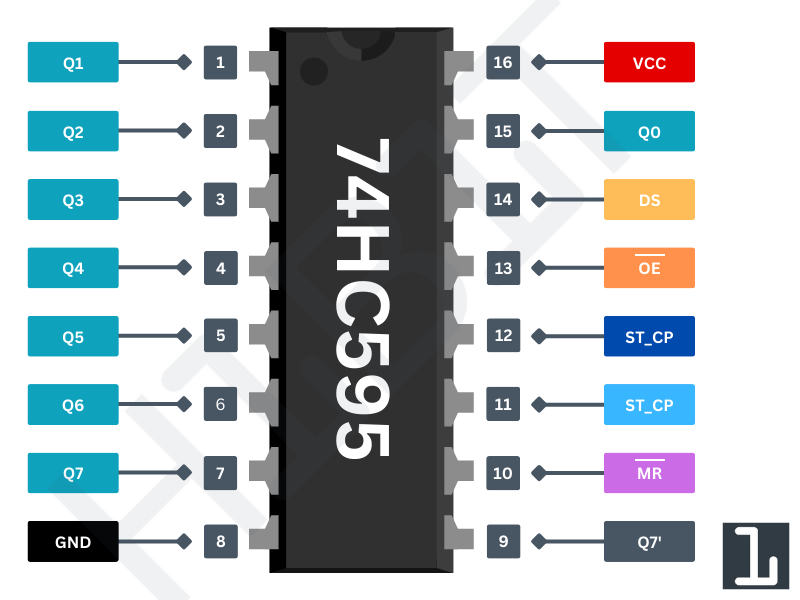
PIN Number | PIN Name | Description |
|---|---|---|
Pins 1-7, 15 | Q0-Q7 | Output pins where the shifted data is sent out |
Pin 8 | GND | Ground pin |
Pin 9 | Q7 | Serial data output for cascading multiple shift registers. |
Pin 10 | MR | Active-low reset, clears all outputs when low. |
Pin 11 | SH_CP | Clock input for shifting data into the register. |
Pin 12 | ST_CP | Latch pin, transfers data to output pins on a rising edge. |
Pin 13 | OE | Active-low output enable, turns outputs on/off. |
Pin 14 | DS | Serial data input to the shift register |
Pin 16 | VCC | Power supply pin (typically +5V) |
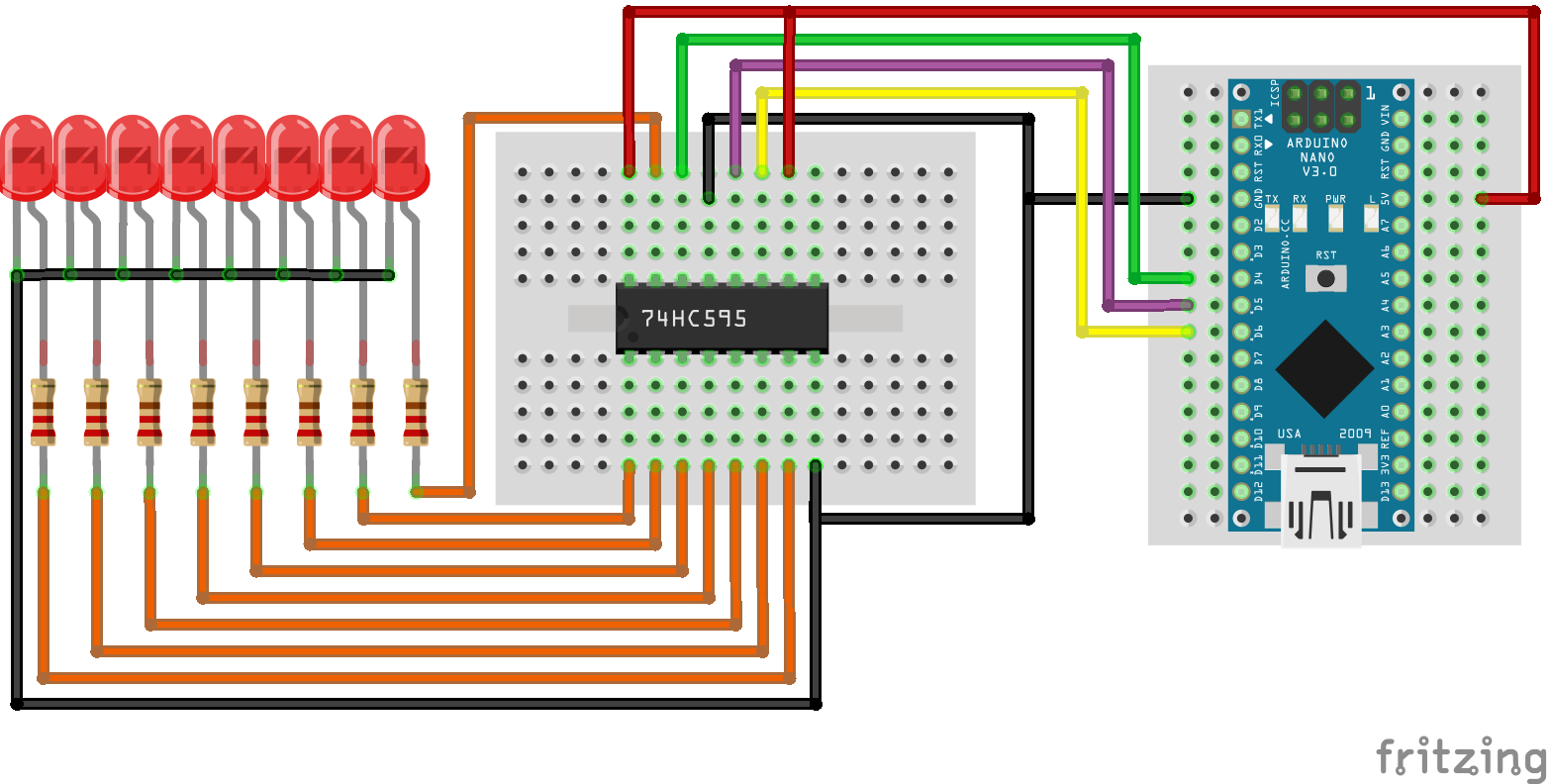
We're going to build a basic circuit with 8 LEDs, which will be controlled by an Arduino using a shift register. Begin by placing the shift register on your breadboard, ensuring that each side of the IC is positioned on opposite sides of the breadboard. With the small U-shaped indentation at the top, pin 1 is located to the left of this indentation.
Connect pin 16 (VCC) and pin 10 (MR) to the Arduino's 5V output, and pin 8 (GND) and pin 13 (OE) to ground. This configuration ensures the IC operates in its normal working mode.
Next, connect the three control pins of the shift register:
Pin 11 (SH_CP) to Arduino pin 6
Pin 12 (ST_CP) to Arduino pin 5
Pin 14 (DS) to Arduino pin 4
The final step is to connect the LEDs to the output pins. Attach the cathode (short pin) of each LED to a common ground, and connect the anode (long pin) of each LED to the corresponding output pin of the shift register. Be sure to include a 220Ω resistor in series with each LED to prevent overloading.
The diagram below illustrates the wiring connections.
Arduino code
Here is a simple sketch that sequentially turns on each LED until all are illuminated, then turns them off and repeats the cycle.
#define DATA_PIN 4
#define LATCH_PIN 5
#define CLOCK_PIN 6

byte leds; // Variable to store the pattern indicating which LEDs are currently on/off

void setup()
{
  // Set pins mode
  pinMode(DATA_PIN, OUTPUT);
  pinMode(LATCH_PIN, OUTPUT);
  pinMode(CLOCK_PIN, OUTPUT);
}

void loop()
{
  leds = 0; // Initially turns off all the LEDs

  sendToShiftRegister(leds);
  delay(500);

  // Iterate LEDs one by one
  for (int i = 0; i < 8; i++) {
    // Set HIGH the current LED in the leds variable
    bitSet(leds, i);

    sendToShiftRegister(leds);
    delay(500);
  }
}

/**
  * This function sends a byte of data to the shift register
  */
void sendToShiftRegister(byte data)
{
  digitalWrite(LATCH_PIN, LOW);
  shiftOut(DATA_PIN, CLOCK_PIN, LSBFIRST, data);
  digitalWrite(LATCH_PIN, HIGH);
}
The code sets up pins to control a shift register for managing LEDs. It initially turns off all LEDs and then sequentially lights each one by updating the shift register with the sendToShiftRegister() function.
Testing
Once everything is properly connected and the code is uploaded, the results should look similar to the video shown below.
The LEDs start in the OFF state and then turn on one by one in sequence before the cycle repeats.
Conclusion
SIPO shift registers are a practical solution for expanding the output capabilities of your Arduino. They allow you to control multiple outputs with minimal pins, making them indispensable for more complex and interactive projects. Understanding and applying SIPO registers can significantly enhance your Arduino setups, leading to more efficient and creative designs.
Credits
Official GitHub: https://github.com/hibit-dev/shift-register


0 Comments