Understanding PISO Shift Registers
Shift registers are integral components in digital electronics, enabling efficient data management and transfer. As your Arduino projects evolve, you might face the challenge of needing to read multiple inputs simultaneously. PISO (Parallel-In, Serial-Out) shift registers provide an elegant solution to this problem. These devices enable you to read several inputs while using only a few pins on your Arduino, making them essential for projects that require a large number of buttons, switches, or sensors. This article explores why shift registers are necessary, how they function, and their practical applications with Arduino.
SIPO vs PISO shift registers
Shift registers are available in two main types: SIPO (Serial-In, Parallel-Out) and PISO (Parallel-In, Serial-Out). SIPO registers are ideal for managing multiple outputs, like controlling arrays of LEDs, whereas PISO registers excel at collecting multiple inputs, such as reading states from buttons.
The 74HC595 is a widely used SIPO chip, while the 74HC165 is the go-to PISO chip.
Components
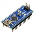
| 1x Arduino Nano (or another Arduino module) $3.30 |
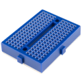
| 1x Mini-breadboard
|
| 1x 74HC165 shift register
|
| 8x Push button
|
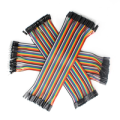
| Dupont wires
|


Understanding PISO shift registers
A PISO shift register works by capturing parallel input data and then shifting it out serially to the Arduino. The process works as follows:
Parallel Data Capture: all the inputs are read simultaneously when a load signal is applied, storing their state in the shift register.
Clock Synchronization: the clock signal synchronizes the shifting of data bits within the register.
Serial Output Transmission: the data is then shifted out, one bit at a time, through a serial connection to the Arduino.
The 74HC165 PISO register typically requires three Arduino pins: Clock (to synchronize data reading), Load (to latch the input data into the register) and Data (to receive the serial output). This setup allows the Arduino to efficiently read the status of multiple inputs without the need for direct connections to each input source, saving valuable pin resources.
Why use PISO shift registers with Arduino?
The limited number of input pins on an Arduino can be a bottleneck in projects where you need to monitor multiple input sources. PISO shift registers, such as the 74HC165, address this issue by allowing you to read multiple parallel inputs and then sending the data serially to the Arduino. This method not only conserves pins but also simplifies the overall circuit, making it ideal for projects like keypads, sensor arrays, or control panels.
Wiring schema
By integrating PISO shift registers into your projects, you can significantly expand the input capabilities of your Arduino, making it possible to handle more complex and interactive designs with ease. Let's begin by reviewing the pinout of the shift register chip.
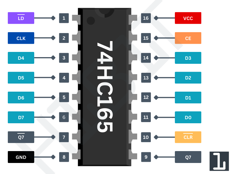
PIN Number | PIN Name | Description |
|---|---|---|
Pins 3-6, 11-14 | D0-D7 | Parallel input pins where the data is loaded into the shift register |
Pin 1 | LD | Active-low load pin, loads parallel data into the register when low |
Pin 2 | CLK | Clock input, shifts data out on the rising edge |
Pin 7 | Q7' | Additional serial data output for cascading multiple shift registers. |
Pin 8 | GND | Ground pin |
Pin9 | Q7 | Serial data output pin, where the data is shifted out. |
Pin 10 | CLR | Active-low clear pin, resets all internal data when low. |
Pin 15 | CE | Disables the clock input when high, preventing data from being shifted. |
Pin 16 | VCC | Power supply pin (typically +5V) |
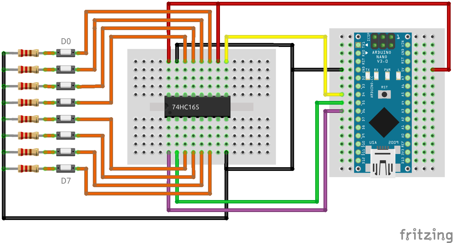
We're going to create a simple circuit with 8 buttons, which will be read by an Arduino using a 74HC165 shift register. Begin by placing the shift register on your breadboard, ensuring that each side of the IC is positioned on opposite sides of the breadboard. With the small U-shaped indentation at the top, pin 1 is located to the left of this indentation.
Connect pin 16 (VCC) to the Arduino's 5V output and pin 8 (GND) to ground. After that, connect pin 15 (CE) to ground to enable clock functionality and pin 10 (/CLR) to 5V to keep the shift register active. This configuration ensures the IC operates in its normal working mode.
Next, connect the three control pins of the shift register:
Pin 1 (/LD) to Arduino pin 6
Pin 2 (CLK) to Arduino pin 5
Pin 9 (Q7) to Arduino pin 4
Finally, attach one side of each button to the corresponding input pins D0-D7 (pins 11-14 and 3-6). Connect the other side of each button to ground through a 10kΩ pull-down resistor to ensure a stable low state when the button is not pressed.
The diagram below illustrates the wiring connections.
Arduino code
Here's a simple Arduino sketch to read the state of 8 buttons connected to the 74HC165:
#define DATA_PIN 4
#define LOAD_PIN 5
#define CLOCK_PIN 6

byte buttonStates; // Variable to store the state indicating which buttons are currently on/off

void setup()
{
  // Begin serial communication with the host computer
  Serial.begin(115200);
  Serial.println();

  // Set pins mode
  pinMode(DATA_PIN, INPUT);
  pinMode(LATCH_PIN, OUTPUT);
  pinMode(CLOCK_PIN, OUTPUT);
}

void loop()
{
  buttonStates = readFromShiftRegister();

  // Print the button states in binary format
  Serial.println(buttonStates, BIN);

  delay(500); // Wait half a second before reading again
}

/**
  * This function reads a byte of data from the shift register
  */
byte readFromShiftRegister()
{
  digitalWrite(LOAD_PIN, LOW);
  delayMicroseconds(5);
  digitalWrite(LOAD_PIN, HIGH);

  byte buttonStates = shiftIn(DATA_PIN, CLOCK_PIN, MSBFIRST);

  return buttonStates;
}
The code reads the state of multiple buttons connected to a 74HC165 shift register and then prints the button states in binary format to the serial monitor. The readFromShiftRegister() function handles reading the button states by shifting in data from the shift register.
Conclusion
PISO shift registers are a powerful tool for expanding the input capabilities of your Arduino. They allow you to monitor multiple inputs using just a few pins, simplifying your project and making it more scalable. By understanding and utilizing PISO registers, you can create more intricate and responsive Arduino projects, enhancing both their functionality and flexibility.
Credits
Official GitHub: https://github.com/hibit-dev/shift-register


0 Comments