Servo controlled pan and tilt platform
A pan-tilt platform is a mechanism used to move a camera, sensor, or other devices in two axes: horizontal (pan) and vertical (tilt). These platforms are often powered by servo motors, which allow for precise control over movement. They're popular in robotics, camera stabilization, and security systems. With an Arduino Nano, everyone can experiment with controlling these movements and integrate them into larger projects.
Prerequisites
it's highly recommended to read how to control servo motor with Arduino to gain a deeper understanding of how servo motors work, the basics of wiring them with an Arduino, and fundamental programming concepts. This will make it easier to follow along and get the most out of building your own pan-tilt platform.
Components
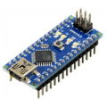
| 1x Arduino Nano (or another Arduino module) $3.29 |
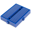
| 1x Mini Breadboard
|
| 2x Micro Servo SG90
|
| 2x Micro Servo MG90S (metal gear) $5.68 |
| 1xServo PT platform
|
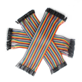
| Dupont wires
|


Servo PT platform
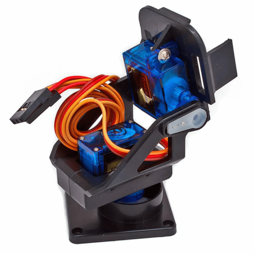
The frame typically consists of two sections: one for horizontal (pan) movement and another for vertical (tilt). The frame can be made using materials such as 3D-printed parts or small metal brackets to achieve a stable, lightweight design. Alternatively, you can use pre-made pan-tilt kits designed for small servo motors, capable of holding lightweight items like cameras, sensors, or even laser pointers.
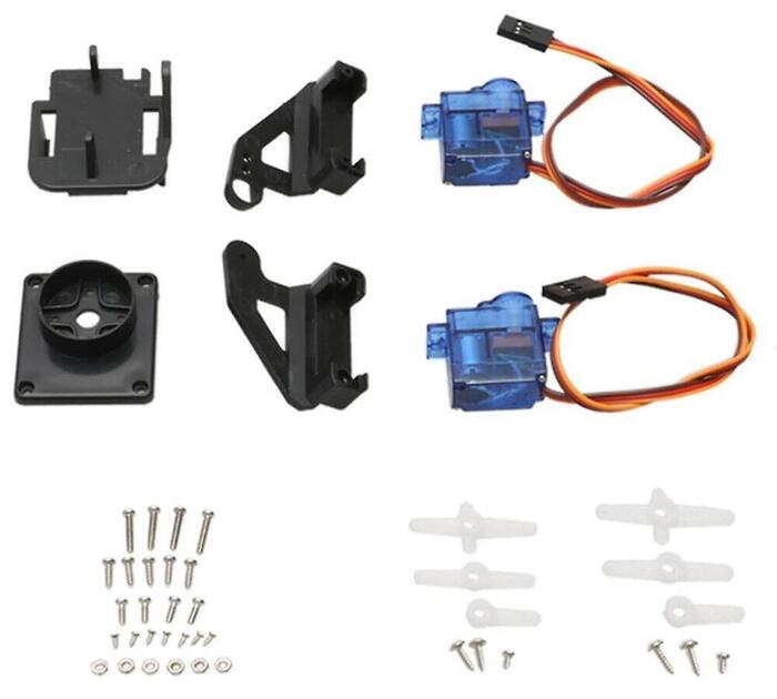
The essential parts of a pan-tilt platform are two servo motors and a frame that holds them in place. One servo motor controls the horizontal movement (pan), while the other controls the vertical movement (tilt).
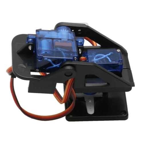
Ensure the platform is balanced and the weight is evenly distributed to avoid straining the servos, which can negatively impact their performance and lifespan. When mounting, confirm that the servos have enough clearance for free rotation. An unbalanced load or excessive weight can lead to increased stress on the motors, potentially shortening their durability.
Wiring schema
In this project, we will use the Arduino Nano as the microcontroller to control the servo motors and ensure the pan-tilt platform operates smoothly. Each servo motor has three key wires: power (VCC), ground (GND), and signal (PWM). Here's how to connect them:
Power (VCC): Begin by connecting the VCC wire from each servo to the 5V pin on the Arduino. This connection supplies the necessary power for the servos to operate.
Ground (GND): Connect the GND wire from each servo to one of the GND pins on the Arduino. This step completes the electrical circuit.
Signal (PWM): The signal wire is vital for controlling the servo's movements. Connect each servo's signal wire to a PWM-capable digital pin on the Arduino. For this project, use pin 9 for the pan servo and pin 10 for the tilt servo.
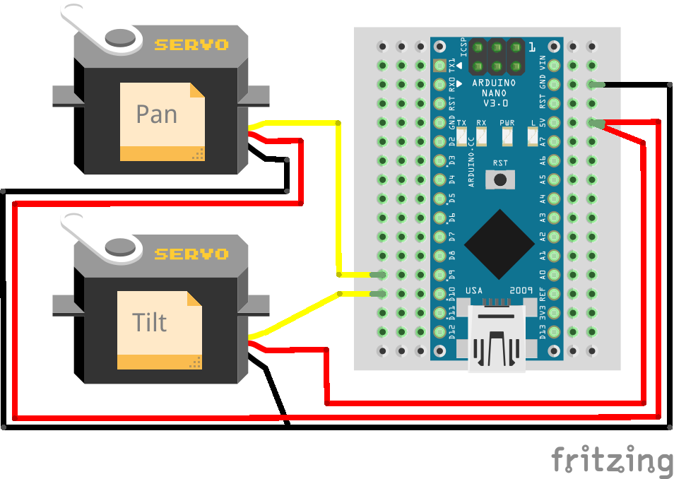
To connect a servo motor to Arduino Nano, the servo motor's control line is connected to one of the PWM enabled digital pins on the Arduino Nano. The servo motor's power and ground are also connected to the power and ground pins on the Arduino Nano, respectively.
Servo motor | Arduino |
|---|---|
Power (red) | 5V |
Ground (brown or black) | GND |
Signal (orange, yellow or white) | Pin 9/Pin10 |
Once the servo motor is connected, the Arduino Nano can send pulse signals to the servo motor to control its position. A servo motor is controlled by sending a series of pulses through the signal line. The width of the pulse is what determines the angular position of the servo, which can typically rotate up to 180 degrees, as it has physical limits. Generally pulses with 1ms duration correspond to 0 degrees position, 1.5ms duration to 90 degrees and 2ms to 180 degrees.
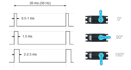
While the duration of the pulses required to control a servo motor is typically standardized, the minimum and maximum pulse durations may vary depending on the specific brand or model of the servo motor being used.
Arduino code
To control the servos, we will use the built-in Servo library, which simplifies the process of sending commands to the motors. This library allows you to set the position of each servo using angles, where 0 degrees is one extreme, and 180 degrees is the other.
Here's an example of how you can write the code to control both servos:
#include "Servo.h"

#define SERVO_PAN_PIN 9
#define SERVO_TILT_PIN 10

#define MIN_ANGLE 0
#define MID_ANGLE 90
#define MAX_ANGLE 180

#define DEFAULT_PAN_ANGLE 0
#define DEFAULT_TILT_ANGLE 0

struct ServoMotion {
  Servo motor;
  int angle;
} pan, tilt;

void setup()
{
  // Attach servo pins
  pan.motor.attach(SERVO_PAN_PIN);
  tilt.motor.attach(SERVO_TILT_PIN);

  // Set default servo angles
  writeServoAngle(pan, DEFAULT_PAN_ANGLE);
  writeServoAngle(tilt, DEFAULT_TILT_ANGLE);
}

void loop()
{
  applyGraduallyServoAngle(pan, MIN_ANGLE);
  delay(1000);
  tiltRange();
  delay(1000);

  applyGraduallyServoAngle(pan, MID_ANGLE);
  delay(1000);
  tiltRange();
  delay(1000);

  applyGraduallyServoAngle(pan, MAX_ANGLE);
  delay(1000);
  tiltRange();
  delay(1000);
}

void tiltRange()
{
  applyGraduallyServoAngle(tilt, MAX_ANGLE);
  applyGraduallyServoAngle(tilt, MIN_ANGLE);
  delay(500);
}

void applyGraduallyServoAngle(ServoMotion &servo, int angle)
{
  int desiredAngle = limitServoAngle(angle);
  int currentAngle = servo.angle;

  while (currentAngle != desiredAngle) {
    if (currentAngle > desiredAngle) {
      currentAngle--;
    } else if (currentAngle < desiredAngle) {
      currentAngle++;
    }

    writeServoAngle(servo, currentAngle);

    delay(10); // Wait 10ms for the servo to reach the position
  }
}

void writeServoAngle(ServoMotion &servo, int angle)
{
  servo.angle = angle;
  servo.motor.write(servo.angle);
}

int limitServoAngle(int angle)
{
  return constrain(angle, MIN_ANGLE, MAX_ANGLE);
}
The code includes a ServoMotion struct to manage each servo's motor and angle. Pins are defined for the servos, along with minimum, middle, and maximum angles. In the setup(), servos are attached to pins and set to default angles. The loop() alternates between moving the pan servo to different angles (minimum, middle, and maximum) and cycling the tilt servo through its range.
The applyGraduallyServoAngle() function adjusts servo angles in small steps to ensure smooth transitions, with the limitServoAngle() ensuring movements stay within predefined angle limits.
Testing
Below you can watch a video demonstration of the servo control system in action. The pan and tilt servos smoothly transition between angles as described in the code, showing how the gradual movement is applied to achieve precise positioning.
Conclusion
Once you've successfully built and programmed the basic pan-tilt platform, there are numerous ways to enhance it. You could add a joystick for manual control or integrate sensors to enable automatic tracking. For example, adding an ultrasonic sensor could allow the platform to track objects based on proximity. If you're into photography or security, mounting a camera on the platform can provide automated panning and tilting to cover more areas.
More advanced programming could involve setting up a feedback loop, where the platform's movement is adjusted in real-time based on sensor inputs. This kind of dynamic control can be especially useful for robotics applications or motion detection systems.
Credits
Official GitHub: https://github.com/hibit-dev/servo


0 Comments