Getting started with RF-Nano and wireless communication
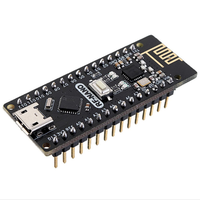
The RF-Nano module is a compact, affordable module that combines an NRF24L01 wireless transceiver with an Arduino-compatible microcontroller. Using the NRF24L01 protocol, the RF-Nano operates on the 2.4 GHz band, making it a practical choice for creating simple, low-power wireless networks. This module is popular among hobbyists and engineers for tasks like home automation, remote control applications, and IoT sensor networks. It’s especially suited for applications where simple, secure data sharing between sensors or remote control devices is required and where a compact, low-cost solution is preferred.
Components
| 2x RF-Nano
|
| 2x Mini-breadboard
|
| RF24 official library |
Wiring schema
The RF-Nano module is ready to function as both a microcontroller and a wireless transceiver, eliminating the need for an external Arduino board. Programming it is straightforward and follows the same process as working with an Arduino Nano.
Connecting the RF-Nano to your computer: use a USB cable to connect the RF-Nano module to your computer. Once connected, select the Arduino Nano as the board type in the Arduino IDE, and choose the appropriate processor type depending on your module.
Writing and uploading code: once the library is installed, you can start programming the RF-Nano using familiar Arduino syntax. The RF24 library includes functions to set up basic send-and-receive functions. After writing your code, upload it to the RF-Nano as you would with any other Arduino board.
Testing communication: To test your RF-Nano, set up a simple communication script to confirm that the module can send and receive data successfully.
This self-contained design makes it an efficient choice for projects that require both processing and wireless communication in a single module.
Install Arduino library for nRF24L01
To interact with the RF-Nano, we will use an existing library. This library, provides an interface that facilitates communication with the module, saving you significant time and providing a reliable and extensively tested code base. It can be downloaded from our official repository.
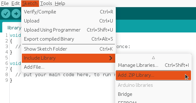
To import a library, open the Arduino IDE, go to Sketch > Include Library > Add .ZIP Library and select the library file downloaded from our GitHub repository.
Then you can simply use include statement:
#include "RF24.h"
#include "nRF24L01.h"
It will include the library with predefined functions to interact with the module.
Programming and setting up the RF-Nano
With its built-in Arduino-compatible microcontroller, the RF-Nano is ready for programming right out of the box. It connects to your computer via USB and is programmed using the Arduino IDE, allowing you to code and configure the RF-Nano module without needing an additional Arduino board.
RF-Nano transmitter code
The transmitter code uses the RF24 module with the nRF24L01 transceiver to send data wirelessly. It includes necessary libraries, defines the CE and CSN pins, and sets a transmission interval of 250 milliseconds. An RF24 object is created with these pins, and a 6-byte address for communication is established.
A payload structure is defined with a byte and a character. In the setup function, serial communication is initialized, and the radio is configured to disable automatic acknowledgment, set the data rate to 250 kbps, and maximize transmission power. The writing pipe is opened with the specified address. In the loop function, the code assigns values to the payload and transmits it using radio.write. It prints the transmitted values to the serial monitor and waits 250 milliseconds before repeating the process.
#include "SPI.h"
#include "RF24.h"
#include "nRF24L01.h"

#define CE_PIN 9
#define CSN_PIN 10

#define INTERVAL_MS_TRANSMISSION 250

RF24 radio(CE_PIN, CSN_PIN);

const byte address[6] = "00001";

//NRF24L01 buffer limit is 32 bytes (max struct size)
struct payload {
  byte data1;
  char data2;
};

payload payload;

void setup()
{
  Serial.begin(115200);

  radio.begin();

  //Append ACK packet from the receiving radio back to the transmitting radio
  radio.setAutoAck(false); //(true|false)
  //Set the transmission datarate
  radio.setDataRate(RF24_250KBPS); //(RF24_250KBPS|RF24_1MBPS|RF24_2MBPS)
  //Greater level = more consumption = longer distance
  radio.setPALevel(RF24_PA_MAX); //(RF24_PA_MIN|RF24_PA_LOW|RF24_PA_HIGH|RF24_PA_MAX)
  //Default value is the maximum 32 bytes
  radio.setPayloadSize(sizeof(payload));
  //Act as transmitter
  radio.openWritingPipe(address);
  radio.stopListening();
}

void loop()
{
  payload.data1 = 123;
  payload.data2 = 'x';

  radio.write(&payload, sizeof(payload));

  Serial.print("Data1:");
  Serial.println(payload.data1);

  Serial.print("Data2:");
  Serial.println(payload.data2);

  Serial.println("Sent");

  delay(INTERVAL_MS_TRANSMISSION);
}
RF-Nano receiver code
The receiver code uses the RF24 module to receive wireless data. It includes the necessary libraries and defines the CE and CSN pins. Constants are set for detecting signal loss and retry intervals.
A payload structure is defined to hold the received data, which includes a byte and a character. In the setup function, serial communication is initialized, and the radio is configured to disable automatic acknowledgment, set the data rate to 250 kbps, and open the reading pipe for the specified address while starting to listen for incoming data.
In the loop function, the code checks for available data. If data is received, it reads the payload, prints the values to the serial monitor, and updates the last signal timestamp. If no signal is detected within a specified interval, the lostConnection function is called to indicate a lost connection and temporarily pause further actions.
#include "SPI.h"
#include "RF24.h"
#include "nRF24L01.h"

#define CE_PIN 9
#define CSN_PIN 10

#define INTERVAL_MS_SIGNAL_LOST 1000
#define INTERVAL_MS_SIGNAL_RETRY 250

RF24 radio(CE_PIN, CSN_PIN);

const byte address[6] = "00001";

//NRF24L01 buffer limit is 32 bytes (max struct size)
struct payload {
  byte data1;
  char data2;
};

payload payload;

unsigned long lastSignalMillis = 0;

void setup()
{
  Serial.begin(115200);

  radio.begin();

  //Append ACK packet from the receiving radio back to the transmitting radio
  radio.setAutoAck(false); //(true|false)
  //Set the transmission datarate
  radio.setDataRate(RF24_250KBPS); //(RF24_250KBPS|RF24_1MBPS|RF24_2MBPS)
  //Greater level = more consumption = longer distance
  radio.setPALevel(RF24_PA_MIN); //(RF24_PA_MIN|RF24_PA_LOW|RF24_PA_HIGH|RF24_PA_MAX)
  //Default value is the maximum 32 bytes1
  radio.setPayloadSize(sizeof(payload));
  //Act as receiver
  radio.openReadingPipe(0, address);
  radio.startListening();
}

void loop()
{
  unsigned long currentMillis = millis();

  if (radio.available() > 0) {
    radio.read(&payload, sizeof(payload));

    Serial.println("Received");

    Serial.print("Data1:");
    Serial.println(payload.data1);

    Serial.print("Data2:");
    Serial.println(payload.data2);

    lastSignalMillis = currentMillis;
  }

  if (currentMillis != 0 && currentMillis - lastSignalMillis > INTERVAL_MS_SIGNAL_LOST) {
    lostConnection();
  }
}

void lostConnection()
{
  Serial.println("We have lost connection, preventing unwanted behavior");

  delay(INTERVAL_MS_SIGNAL_RETRY);
}
Testing
Keep in mind that we need to create two circuits with the same wiring. First, we will upload the transmitter code, which will generate the message payload and send it at each INTERVAL_MS_TRANSMISSION. Next, we will upload the receiver code, which will listen for the message payload and process it. The serial monitor will display output similar to:

The final line indicates a lost connection after INTERVAL_MS_SIGNAL_LOST milliseconds without a signal. In this instance, it was expected behavior. In real situations, the signal can be lost for various known and unknown reasons, so we need to manage this and implement corrections in the lostConnection() function.
Conclusion
The RF-Nano module is a practical choice for simple, cost-effective wireless communication. Its compact size, low power consumption, and Arduino compatibility make it a good fit for home automation, remote monitoring, and IoT projects.
Credits
Official GitHub: https://github.com/hibit-dev/nrf24l01
Official nRF24 GitHub: https://github.com/nRF24




0 Comments