DYI - Programmed Christmas lights
Take your holiday decorations to the next level with a custom fairy light display powered by an Arduino Nano. This project blends creativity and basic electronics, allowing you to program fairy lights with unique patterns and effects that reflect your personal style. By replacing generic, store-bought solutions with something custom-made, you’ll create a decoration that’s not only festive but truly one of a kind. With accessible components and straightforward steps, it offers an engaging way to add warmth and charm to your holiday season.
Programmed Christmas lights project
Programmed Christmas lights: concept
Programmed Christmas lights: mounting
Programmed Christmas lights: code
Components
| 1x Arduino Nano (or another Arduino module) $3.38 |
| 1x Mini-breadboard
|
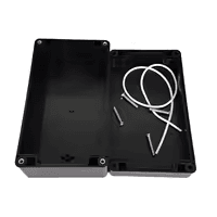
| 1x Black container (83x58x33)
|
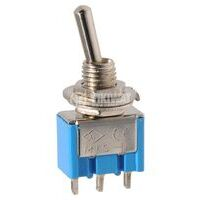
| 1x Switch button $3.21 |
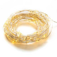
| Fairy lights
|
| Dupont wires
|
| 9V Battery clip + 9V Battery
|
Prerequisites
We suggest reviewing articles that are either directly or indirectly referenced in this guide. This will provide you with a comprehensive understanding of each component and how they interact.
Setting up custom Christmas lighting
For this project, we’ll use 5V fairy lights, which are lightweight, flexible, and straightforward to work with. These lights come pre-wired, making them easier to set up without the need for complex connections. If you decide to use other types of lighting, be sure to check their voltage requirements, as higher-voltage options might need an external power source or additional components like a voltage regulator.
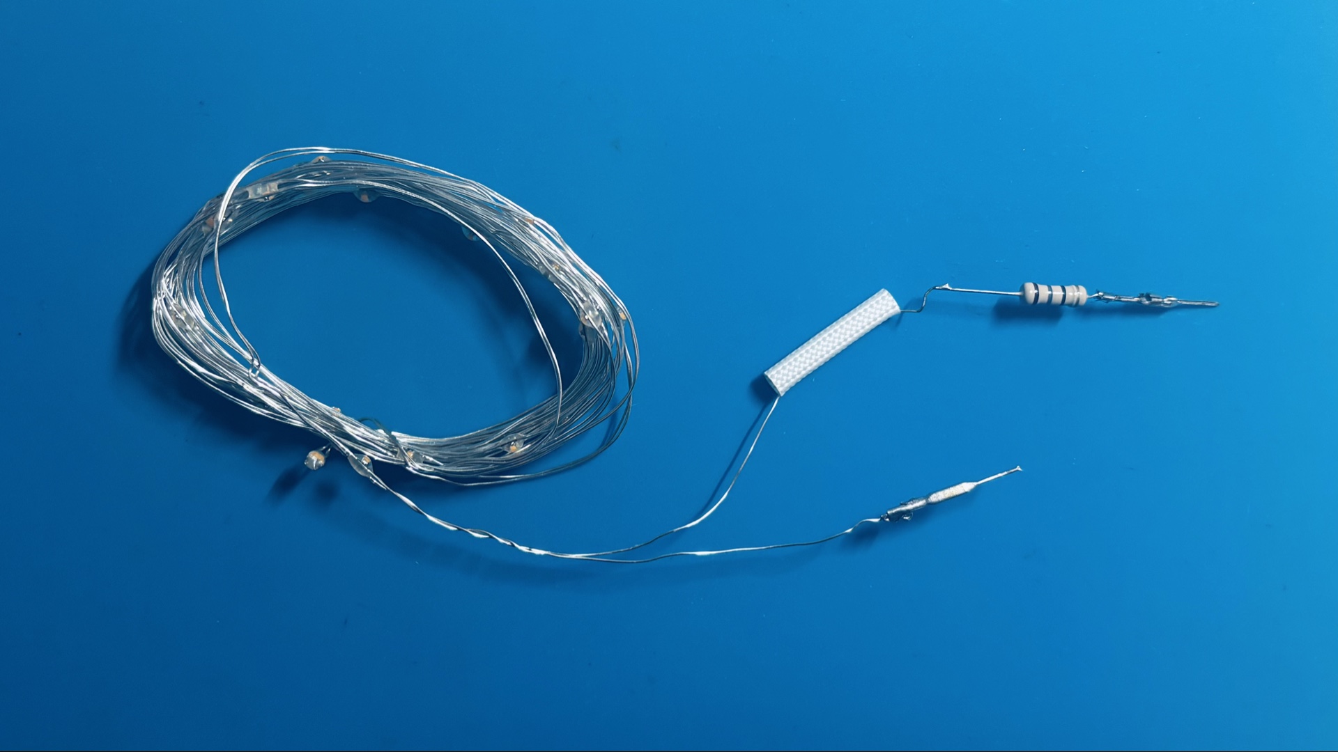
To mount the fairy lights, you can use tape, clips, or hooks, depending on the surface. Start by cleaning the surface and planning the layout to ensure the lights are evenly spaced and the cables are neatly arranged. Also, keep in mind where the Arduino Nano and the power source will be placed for a tidy and efficient setup.
Adding the Arduino controller
The Arduino Nano acts as the controller for the fairy lights, giving you the ability to adjust their brightness and create custom blinking patterns. To set this up, connect the power wire of the fairy lights to one of the Arduino’s PWM (Pulse Width Modulation) output pins. This connection allows for precise control over the intensity and effects of the lights.
Make sure the ground wire of the fairy lights is firmly connected to the ground pin on the Arduino. Since fairy lights typically have lower power requirements, they can often be powered directly by the Arduino without needing an external power source. However, it’s essential to verify the current draw of your specific lights to ensure they are compatible with the Arduino’s power limits.
Setting up the power source
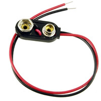
A 9V battery will power the Arduino Nano, supplying enough energy for both the microcontroller and the fairy lights. The battery connects to the Arduino using a 9V battery clip, which provides a secure and reliable connection to the power input. To enhance convenience, a switch button is included in the circuit, allowing for easy on/off control of the entire setup. Dupont wire connectors are used to streamline the wiring process, enabling quick and solder-free connections to the breadboard.
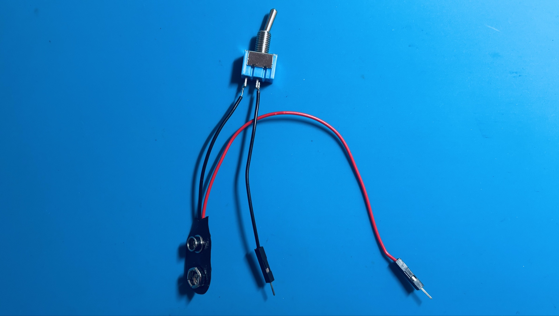
The fairy lights in this project have low power consumption, allowing them to draw power directly from the Arduino without the need for an external power source. However, if you decide to use a larger set of lights or those with higher power demands, an external power source may be necessary to prevent issues like overheating or dim lighting. Always verify the current and voltage requirements of your fairy lights to ensure compatibility with your power setup for safe and stable operation.
Protecting the setup with a case
To give the custom lighting project a polished look, all components are housed in a black container box. This box is carefully selected to fit the Arduino Nano, the 9V battery, and the wiring, keeping all the electronics neatly concealed. By hiding the circuit inside the box, the setup appears clean and professional, making it perfect for display in any holiday setting.
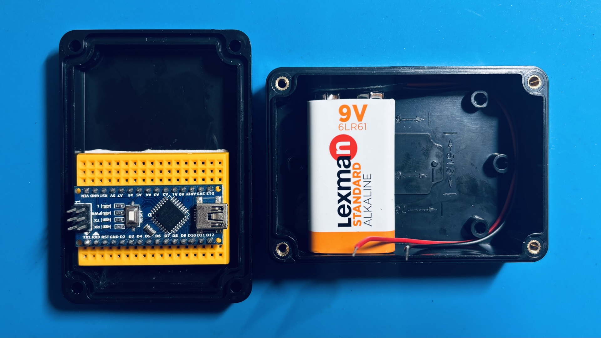
Both the 9V battery and the mini breadboard are secured inside the container using double-sided tape. This ensures the components remain firmly in place, preventing any shifting or disconnections during use or handling. The Arduino Nano, mounted on the breadboard, also benefits from this stable setup, which helps maintain reliable connections and an organized arrangement.
Wiring schema
For this project, we will use the D3 pin on the Arduino Nano as the control output, utilizing its PWM capability to adjust the brightness and create blinking effects. The fairy lights we’re using are designed to work directly with a 5V source, as they already have a built-in resistor. If your fairy lights lack a resistor, be sure to add one to prevent potential damage from excess current. Always verify the specifications of your components before beginning the setup to ensure compatibility and safety.
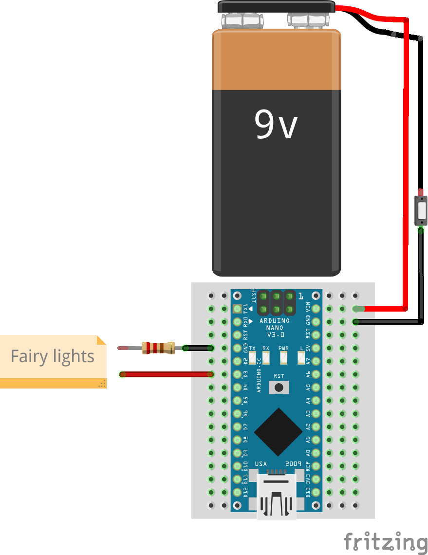
In the wiring diagram above, the positive wire from the fairy lights is connected to the D3 pin on the Arduino Nano, while the ground wire is linked to the Arduino's GND pin. The 9V battery is connected to the VIN and GND pins on the Arduino, providing power to both the microcontroller and the fairy lights.
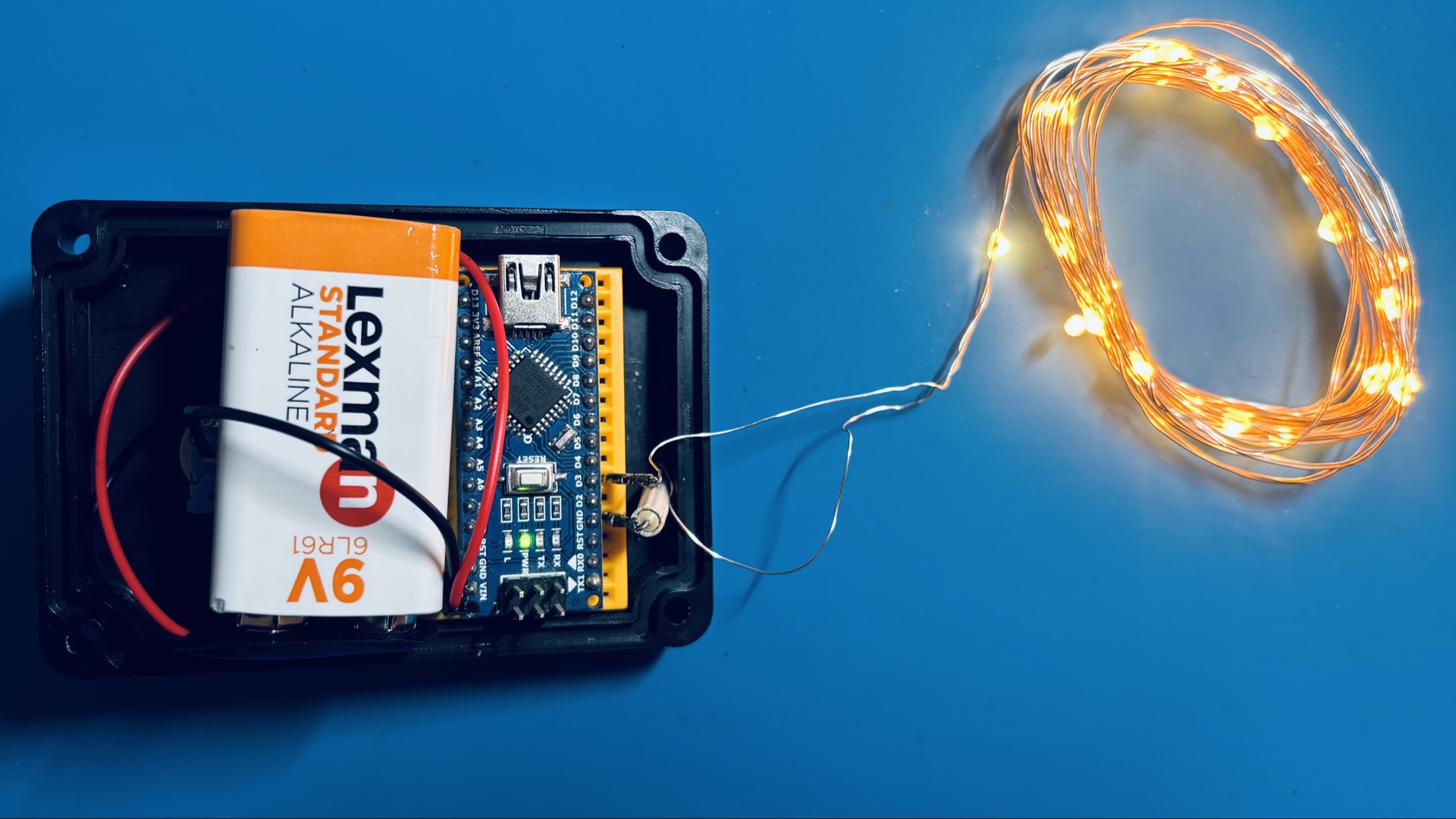
The final overview image offers a clear view of the completed setup, highlighting how all the components are connected. With the wiring securely arranged and everything enclosed within the container, the system is fully assembled and ready for operation. This layout not only ensures the functionality of the project but also maintains a clean and organized appearance, making it easy to maintain or adjust in the future.
Arduino code
The provided code is designed with simplicity and modularity in mind, making it easy to adapt and expand. Below is the main structure:
#define LED_PIN 3

void setup()
{
  pinMode(LED_PIN, OUTPUT);
}

void loop()
{
  // Program + delay
  program1(LED_PIN);
  delay(1000);

  // Program + delay
  program2(LED_PIN);
  delay(1000);

  // Program + delay
  program3(LED_PIN);
  delay(1000);
}
LED_PIN: defines the pin used to control the fairy lights. Here, it’s pin D3, which supports PWM output.
Setup function: prepares the LED_PIN as an output to ensure proper control of the lights.
Loop function: executes the lighting programs (
program1,program2,program3) in sequence, each followed by a delay to give a clear pause between routines.
The lighting routines are kept in a separate file for better organization and flexibility. This setup makes it easy to introduce new routines or modify existing ones without altering the main structure.
Program 1
Activates the lights for 5 seconds before turning them off.
void program1(int ledPin)
{
  digitalWrite(ledPin, HIGH);
  delay(5000);
  digitalWrite(ledPin, LOW);
}
Program 2
Smoothly increases and decreases the brightness of the lights five times using PWM.
void program2(int ledPin)
{
  int iterations = 0;

  while (iterations < 5) {
    increaseLight(ledPin);
    delay(500);
    decreaseLight(ledPin);

    iterations++;
  }
}
Program 3
Creates a blinking effect, turning the lights on and off 10 times.
void program3(int ledPin)
{
  int iterations = 0;

  while (iterations < 10) {
    digitalWrite(ledPin, HIGH);
    delay(250);
    digitalWrite(ledPin, LOW);
    delay(250);

    iterations++;
  }
}
Customizing the Code
This modular approach makes it easy to add new routines or modify existing ones. If you want to create a breathing light effect, alternate patterns, or design a custom rhythm, just define a new function and call it within the loop. The possibilities are as wide as your creativity.
Testing
Testing ensures that everything works as expected. Once wired and programmed, power up your setup and watch the lights cycle through the routines. This step is essential to confirm that the wiring, power supply, and code are all functioning properly.
If any adjustments are needed, check the connections or tweak the code. Testing also serves as an opportunity to refine your design and experiment with new ideas.
Conclusion
This project is more than just a decoration - it's a fun, hands-on experience that allows you to express your creativity. From the satisfaction of assembling the hardware to programming your unique light patterns, every step is a chance to make something special. So, gather your materials, start building, and light up the holidays with your one-of-a-kind display!
Credits
Official GitHub: https://github.com/hibit-dev/fairy-lights



0 Comments