Using a motion sensor with Arduino
Motion sensors are essential in modern automation projects, playing a key role in security systems, smart lighting, and interactive devices. These sensors detect movement and trigger specific actions, making them useful for various applications. When paired with an Arduino, a motion sensor can be programmed to respond intelligently, creating an efficient and responsive system. This guide explains how motion sensors work, how to connect them to an Arduino, and how to write the code needed to make them function properly.
Components
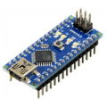
| 1x Arduino Nano (or another Arduino module)
|
| 1x Mini-breadboard
|
| 1x Motion sensor $1.60 |
| Dupont wires
|


How a PIR motion sensor works
The most common motion sensor is the Passive Infrared (PIR) sensor. It detects infrared radiation emitted by warm objects, such as humans and animals. When movement is detected, the sensor sends a signal that can be used to trigger an action, such as turning on a light or sounding an alarm.
Most PIR sensors have two adjustable settings:
Sensitivity: determines how much movement is needed to activate the sensor.
Delay time: controls how long the sensor remains triggered after motion is detected.
By adjusting these settings, the sensor can be fine-tuned for different environments, preventing false triggers and improving accuracy.
Configuring trigger modes
Some PIR sensors have a small jumper, usually located in the top right corner, labeled H and L. This jumper allows you to switch between two trigger modes:
H (Repeatable Trigger Mode): in this mode, the sensor continuously sends a HIGH signal as long as motion is detected. The output remains HIGH, and the LED (or any connected device) stays on while movement is present. Once no motion is detected, the signal goes LOW.
L (Single Trigger Mode): the sensor sends a HIGH signal when it first detects motion, but it does not reset if movement continues. The output stays HIGH for the configured delay time, then turns LOW, even if there is still motion.
Using Repeatable Trigger Mode (H) is useful for applications where continuous motion should keep a system active, such as security alarms or automatic lighting. Single Trigger Mode (L) works better for cases where a fixed activation period is needed regardless of ongoing movement.
Wiring schema
Wiring a PIR sensor to an Arduino is simple, requiring just three connections:
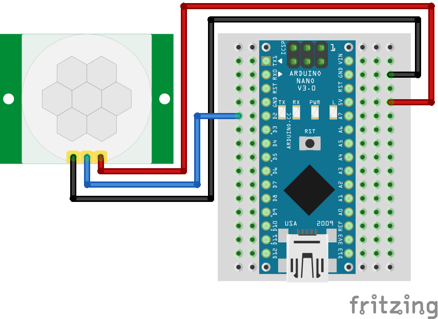
VCC (Power): provides power to the sensor. It should be connected to the 5V or 3.3V pin on the Arduino, depending on the sensor's voltage requirements.
GND (Ground): serves as the ground connection and should be connected to the GND pin on the Arduino.
OUT (Signal Output): sends a digital signal (HIGH or LOW) to the Arduino when motion is detected. It should be connected to one of Arduino's digital input pins.
Ensure the sensor is positioned properly, avoiding direct exposure to heat sources like sunlight or heaters, as these can cause false triggers. The detection range and angle of the sensor depend on the model used but are generally around 5 to 7 meters with a 120-degree field of view.
Arduino code
Once the sensor is connected, the Arduino needs a simple program to detect motion and trigger a response. The following code reads the PIR sensor's output and turns on the built-in LED when motion is detected.
#define PIR_PIN 2
#define LED_PIN 13

void setup()
{
  Serial.begin(115200);

  pinMode(PIR_PIN, INPUT);
  pinMode(LED_PIN, OUTPUT);
}

void loop()
{
    int motion = digitalRead(PIR_PIN);

    if (motion == HIGH) {
        Serial.println("Motion detected!");

        digitalWrite(LED_PIN, HIGH);

        delay(2000);
    } else {
        digitalWrite(LED_PIN, LOW);
    }
}
The PIR sensor is connected to digital pin 2, while the built-in LED is on pin 13.
The
setup()function initializes the sensor, LED, and serial monitor.The
loop()continuously checks if the sensor detects motion. if motion is detected, the LED turns on and a message is printed in the serial monitor.The delay of 2000ms (2 seconds) prevents excessive triggers.
This setup can be modified by replacing the LED with other components like a buzzer, relay module, or Wi-Fi module to send alerts remotely.
Testing motion sensor
Once the hardware is connected and the code is uploaded, the system can be tested using the Arduino serial monitor. When motion is detected, the sensor sends a HIGH signal, turning on the LED and printing Motion detected! in the serial monitor. If no motion is present, the LED remains off and no message appears.
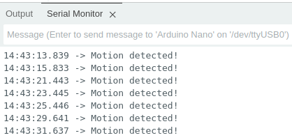
Observing the serial monitor output is a useful way to confirm that the sensor is working correctly and to troubleshoot any issues if the expected behavior is not occurring.
Conclusion
Using a motion sensor with Arduino is an effective way to create automated and interactive systems. It can be applied to security alarms, automatic lighting, and smart home automation. The setup can also be expanded with additional components like buzzers, LCD screens, or wireless modules for enhanced functionality. With a few components and simple wiring, motion sensors can add convenience, efficiency, and security to various projects.
Credits
Official GitHub: https://github.com/hibit-dev/motion-sensor


0 Comments