circuit


Controlling a LED with Arduino

  • avatar
  • 2.0K Views
  • 6 mins read
Preview post image

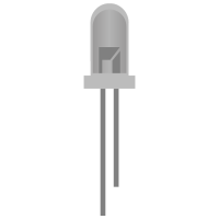
Light Emitting Diodes (LEDs) are incredibly adaptable components often employed in electronics projects for various purposes, from indicating status to creating captivating lighting effects. When it comes to managing LEDs with an Arduino, you have the option of utilizing either digital pins or Pulse Width Modulation (PWM) pins. In this article, we'll explore the advantages of each method and provide you with a comprehensive guide on how to control LEDs using an Arduino.

Using switch buttons with Arduino

  • avatar
  • 2.5K Views
  • 3 Likes
  • 4 mins read
Preview post image

Let's speak now about switch buttons, the wiring and how to implement the code for this circuit elements in Arduino. Switch buttons connect two points in a circuit when you press them and maintain the state without the need to keep the button pressed. That means that logic state of the circuit change every time you press the button.

Using touch sensor with Arduino

  • avatar
  • 2.3K Views
  • 4 mins read
Preview post image

Touch sensor (also known as touch button) is widely used to control devices. It detects touch, force or pressure on its surface changing the logic state of the circuit. Actually, it works in very similar way as to buttons. Checkout the wiring and Arduino code implementation to track the current state and the state changes.

 Join Our Monthly Newsletter

Get the latest news and popular articles to your inbox every month

We never send SPAM nor unsolicited emails

Connecting a motor to Arduino

  • avatar
  • 1.9K Views
  • 1 Like
  • 7 mins read
Preview post image

Arduino microcontrollers are the heart of countless DIY projects, from robots to automated systems. To bring these projects to life, you often need to interface them with motors. In this guide, we'll walk you through the essential steps of connecting a motor to an Arduino using a separate power supply while ensuring control with precision using an NPN transistor. This approach allows you to harness the full potential of your motorized creations without overloading your Arduino.

Pull-up and Pull-down resistors

  • avatar
  • 2.5K Views
  • 4 mins read
Preview post image

A resistor is a passive two-terminal electrical component that implements electrical resistance as a circuit element. In electronic circuits, resistors are used to reduce current flow and adjust signal levels among other uses. Resistance is measured in Ohm with a sign of Ω.

A microcontroller (e.g. Arduino) utilizes I/O signals for communication with external hardware devices, where the most commonly known being GPIO. As a reminder, digital logic circuits have three logic states: high, low and floating (or high impedance). When there’s nothing connected to your GPIO pins, your program will read a floating impedance state, which we do not want. To achieve either high or low states, we’ll have to implement pull-up or pull-down resistors in our digital circuit.

Connecting tilt sensor with Arduino

  • avatar
  • 1.6K Views
  • 1 Like
  • 5 mins read
Preview post image

A tilt sensor is a type of sensor that can detect the orientation or tilt of an object relative to the force of gravity. It works by measuring the change in angle of the object with respect to the vertical axis.

Tilt sensors can be found in various forms, such as simple mechanical switches, mercury switches, and electronic sensors. They are commonly used in applications that require the detection of tilting or changes in orientation, such as in construction equipment, automotive safety systems, robotics, and gaming controllers.

Regulated power supply module based on AMS1117

  • avatar
  • 1.7K Views
  • 5 Likes
  • 3 mins read
Preview post image

We often use the power supplies like batteries or direct AC/DC supply which are normally in higher ranges compared to the actual requirement for the circuit. In that cases we need this kind of voltage regulators which can regulate and vary the voltage levels for the circuit requirement.

The AMS1117 series of chips are linear voltage regulators with low voltage drop. The modules based on the AMS1117 chip provide constant 3.3V or 5V outputs from an unregulated DC input. It's very compact and can be included in your project schema or you can use it together with a breadboard for circuit testing.

Simple steps for building circuits with breadboards

  • avatar
  • 499 Views
  • 6 mins read
Preview post image

A breadboard is an essential tool for working with electronics. It provides a quick and convenient way to test, build, and modify circuits without soldering. Named after the wooden boards originally used to organize components, modern breadboards are plastic boards filled with a grid of tiny holes and internal connectors. This structure lets you easily plug in components and wires, making it ideal for experimenting and prototyping before committing to a permanent setup.

Controlling fan speed with Arduino using a potentiometer

  • avatar
  • 172 Views
  • 5 mins read
Preview post image

Adjusting a fan's speed using an Arduino is a great way to learn about PWM (Pulse Width Modulation) and motor control. With just a potentiometer and some simple wiring, you can create a smooth, manual speed adjustment system. This setup is useful for cooling electronics, ventilation projects, or any application where adjustable airflow is needed.